MAQ20-BRDG1, Strain Gage Bridge Module
Tech Note
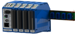
MAQ20 modules are designed for installation in Class I, Division 2 hazardous locations and have a high level of immunity to environmental noise commonly present in heavy industrial environments.
The MAQ20 Data Acquisition System uses an automated registration process which periodically scans the system and will detect when MAQ20 I/O modules are added and removed. ReDAQ Shape provides a graphical representation of system which displays I/O modules sequentially in the order they were registered. The Acquire Panel graphic shows up to 24 registered modules.
- The MAQ20 strain gage input module has 4 input channels and can interface to full, half, and quarter bridge sensors using 4-wire or 6-wire connections.
- All channels are individually configurable for range, alarms, and averaging to match the most demanding applications.
- In addition, sampling rate, resolution, bandwidth, excitation voltage, and shunt calibration are user settable parameters.
- Excitation voltages of 2.5, 3.333, 5.0, and 10.0 Volts.
- Bridge resistances of 100 to 1000 Ohm.
- High, Low, High-High and Low-Low alarms provide essential monitoring and warning functions to ensure optimum process flow and fail-safe applications.
- Hardware low-pass filtering in each channel provides rejection of unwanted frequencies.
- Three internal shunt calibration resistors and software operated switches are provided. External shunt calibration resistors may be user connected.
- Five front panel LED’s for power, alarm, transmit, receive, and status.
- Field I/O connections are made through spring cage terminal blocks with positions designated for the termination of wiring shields.
- 24 bit ADC. The MAQ20-BRDG1 module has a factory default input signal range of -0.100V to +0.100V at the default signal gain setting of 1. 24-bit data conversion provides a high level of accuracy and resolution over this signal range and this setting should be sufficient for most applications.
- The signal gain setting can be changed independently for each channel to 1, 2, 4, 8, or 12 which changes the full scale input signal range to ±100mV, ±50mV, ±25mV, ±12.5mV and ±8.33mV respectively. Over-range and Under-range up to 2% beyond the specified input values will be measured.
- Accuracy including linearity, hysteresis, and repeatability is +/-0.03%. Linearity is +/-0.01%. Resolution 0.0005 to 0.005% span.
- Temperature stability 50ppm per degree Centigrade. -40 to +85C operation.
- Sampling Rate, Simultaneous, 1k to 64k samples per second burst mode.
- Bandwidth is programmable to 17kHz. Common mode rejection 100dB at 50 or 60Hz. Normal mode rejection 60dB per decade beyond cutoff.
- The standard mode of operation is called Continuous Scan Mode. All channels are enabled and input readings are taken by sending a read request command to the module. In Burst Scan Mode, channels can be selectively enabled.
- Input-to-Bus isolation is a robust 1500Vrms
- Each individual channel, both signal and excitation, is protected up to 30Vrms continuous overload in the case of inadvertent wiring errors. Transient protection per ANSI/IEEE C37.90.1. Overloaded channels do not adversely affect other channels in the module which preserves data integrity.
- CE Compliant, UL/CUL Listing and ATEX Compliance.
- 3 year warranty.
For details on hardware installation, configuration, and system operation, refer to the manuals and software available at the MAQ20 Download Center.
Extensive additional reading about strain gages and their use may be found in these Dataforth application notes:
- Basic Bridge Circuits (AN117)
- Strain Gage Signal Conditioner (AN118)


