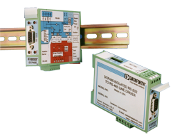
5B isoLynx® - SLX200
Data Acquisition System
Certifications
Documents
 3D CAD Models
Product Availability
Usually stock to 3-5 weeks. Contact Customer Service for current lead times.
PRICING
Use the System Builder to create your own SLX200 System.Please call Dataforth for configuration assistance:
» Applications Engineering
» Phone: 520-741-1404 option 2
System purchases may be entered directly on the factory:
» sales@dataforth.com
» Phone: 520-741-1404 option 1
» Fax: 520-917-2254
For general information, see the SCM5B isoLynx® SLX200 Press Release.
SLX270/280 User Manual Downloads
User Manuals and Software for the SLX200 data acquisition system can be found in the SLX200 Download Center.Features
- Modbus® RTU Support on RS-232 and RS-485
- Modbus TCP Support (optional)
- 1500Vrms Input-to-Output & Channel-to- Channel Isolation
- 240Vrms Field-side Protection
- 16-Bit A/D, D/A
- Up to 6-Pole Analog Input Filtering
- ± 0.012% Base System Accuracy, No Modules
- ± 0.005% Base System Linearity, No Modules
- ± 0.03% Module Accuracy
- ± 0.005% Module Linearity
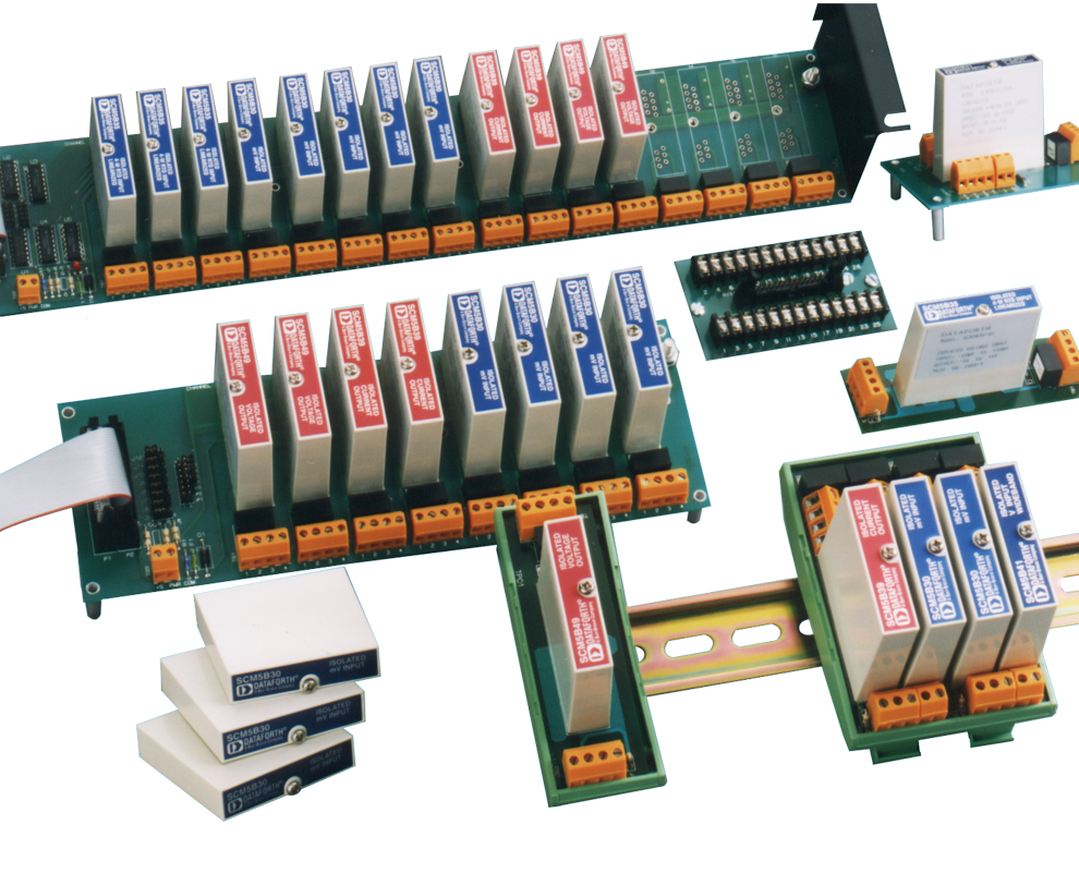
- Best I/O Selection: 250+ Different I/O Modules
- -40°C to +85°C Operating Temperature
- Free Configuration Software
- All Analog I/O Modules Certified to CSA C/US, CE, and ATEX Requirements
- SLX200 & SLX101 CE Compliant
- SLX200 CSA C/US Certified (Class I, Division 2, Groups A, B, C, D)
- Manufactured per RoHS II Directive 2011/65/EU
Products and Ordering
Software Samples
| PartNumber | Description | Purchase License | Download | User Manual | Version | Download Size |
|---|---|---|---|---|---|---|
| - | C++, C sharp, VB.Net Examples | Free | 1.9 | 779.2 KB | ||
| - | LabVIEW VIs | Free | 1.9 | 743.1 KB |
|
C++, C sharp, VB.Net Examples
Free
Version: 1.9
Size: 779.2 KB
|
|
LabVIEW VIs
Free
Version: 1.9
Size: 743.1 KB
|
Hardware Configuration Software
| PartNumber | Description | Purchase License | Download | User Manual | Version | Download Size |
|---|---|---|---|---|---|---|
| - | Hardware Configuration Software | Free | 1.9 | 1.3 MB |
|
Hardware Configuration Software
Free
Version: 1.9
Size: 1.3 MB
|
Demonstration Equipment Software
| PartNumber | Description | Purchase License | Download | User Manual | Version | Download Size |
|---|---|---|---|---|---|---|
| - | Suitecase Demo | Free | 1.9 | 41.3 KB |
|
Suitecase Demo
Free
Version: 1.9
Size: 41.3 KB
|
Manuals
| Description | Version | Download Size |
|---|---|---|
| 335.5 KB | ||
| 7.9 MB | ||
| 1.3 MB | ||
| 480.1 KB | ||
| 537.1 KB | ||
| 9.3 MB |
FAQ
Due to resource constraints on my computer, I'm unable to open the three dimensional CAD models provided on your website. Does Dataforth provide two demensional CAD models for download as well?
Two dimensional CAD models can be generated upon customer request. Please contact Customer Service for assistance.
Is the calibration of Dataforth modules traceable to NIST standards?
Yes, calibration of Dataforth modules is traceable to NIST standards.
How does the load resistance of a module affect the noise at the output?
Noise at the output of a module is independent of load resistance.
How do I convert an RMS voltage to its corresponding peak voltage?
To convert an RMS voltage to its corresponding peak voltage, you simply take the RMS voltage value and multiply it by the square root of 2, or roughly 1.414.
For example, 1500Vrms corresponds to a peak voltage of 1500 * 1.414 = 2121 Vp
Analog Devices announced a last time buy and discontinuance of their signal conditioning modules. Can I replace them with Dataforth signal conditioning modules?
Yes, in general, Dataforth signal conditioning modules are a direct replacement for all Analog Devices signal conditioning modules. e.g. "SCM5B35-xx: Linearized 4-Wire RTD Input Modules" will replace Analog Devices "5B35: Isolated 4 Wire RTD Input Signal Conditioning Module".
Please note that Dataforth signal conditioning modules are RoHS II compliant.
Can Dataforth provide calibration reports for modules I purchased?
Yes we can provide calibration reports for the modules that you purchased.
You can either
a) visit https://www.dataforth.com/TestDataReport.aspx to search for Test Report Datasheets by Serial Number or
b) you can send us a list of model numbers and their serial numbers to support@dataforth.com
With RS-485 communicating to SLX200 I get timeout errors.
You must put the SLX200 into a known communications state. To do this, with the SLX200 powered, pull the CRST jumper off both pins then re-install the jumper over both pins. To locate the CRST jumper, open or download the SLX200 H/W User Manual from the Media Attachments box to the right of this Content box and refer to Section 6.3.
Then power cycle the SLX200. This resets the communications interface to Factory Default conditions.
Communications Interface: RS-232
Device ID: 31
Data Rate: 19.2kbps
Parity: Even
Plug an RS-232 cable into the RS-232 RJ-45 port on the SLX200. Using the SLX200 Configuration Software, in the top tool bar, click on Configure, then click on Modbus RTU Interface. In the RS-232 text window, click on the down triangle and click on the desired RS-485 2-wire or RS-485 4-wire. Click on the Configure button.
Disconnect the RS-232 cable. Power cycle the SLX200. Plug the RS-485 cable into the RS-485 RJ-45 port on the SLX200. Start sending Modbus functions to the SLX200.
Was this content helpful?
Thank you for your feedback!


