Signal-to-Noise Ratio, SNR
Tech Note
The ratio of an information signal to the noise associated with observing this signal is a figure of merit that describes the quality of a communication system.
Consider for example the Voyager 2 Space Craft, which was launched in 1977 and has reached a milestone of 10,000 days (27.4 years) since launch. Voyager 2 is about 7 billion miles from our sun and has transmitted trillions of data bits back to NASA. It is heading out of our solar system with instrumentation continuing to return data. Voyager 2 is expected to operate until the year 2020, a total of 43 years in flight.
Dataforth does not design and manufacture to NASA spacecraft specifications, which would certainly be cost prohibitive for the industrial market. Dataforth nonetheless does use the highest possible standards of quality design, component selection, and manufacturing processes in their product line. Signal conditioning modules (SCMs) from Dataforth are second to none in quality and price.
The signal transmitter power on Voyager 2 is surprisingly small compared to the transmitting power of local radio and TV stations here on earth and yet NASA successfully receives information sent from 7 billion miles away with 1977 vintage electronics, WOW! As an interesting side note, radio signals traveling near the speed of light (186,000 mi/sec), take about 10 hours to travel 7 billion miles. Imagine all the electronic and space noise that accompanies Voyager data transmission and reception.
Noise sources abound, for example, noise from sensors, noise in the signal conditioning electronics, noise in the transmitter, noise from the space, noise in the receiving antenna, noise in the receiver circuits, noise(error) in the software algorithms used to extract data from signals, etc, etc. Signal-to-noise ratio is certainly an important design parameter associated with communication transmitting and receiving systems.
The math associated with the calculating total communication system SNR can get complicated; however, the basic definition is straightforward. The basic mathematical definition of SNR is:
SNR = 10*Log(Signal Power / Noise Power) , or
SNR = 20*Log(Signal Voltage, rms / Noise Voltage, rms)
Calculating the actual signal and all the noise voltage sources can be complicated. As one example, consider an analog to digital converter, ADC unit associated with data acquisition. These units inject “quantization nose” since there is quantization conversion uncertainty of ± LSB/2. An N-bit ADC with a sinusoidal signal input has a signal- to-noise ratio . If this ADC is operated in the over sampling mode, then the signal-to-noise ratio is given by SNR = 6.02*N+1.76 dB + Log(OSR), where OSR (over sampling ratio) is defined as the ratio of sampling frequency (fs) to twice the bandwidth limited signal frequency (fo) , OSR=fs / 2*fo. These simple examples illustrate that as communication systems become more complex, accurately calculating SNR becomes equally complicated.
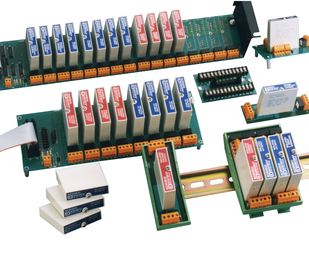
Although the SNR as a figure of merit does not generally apply to industrial process instrumentation and control modules, one can calculate a basic number from Dataforth specifications. For example, Dataforth’s SCM5B30 Analog Voltage Input Module, Narrow Bandwidth has a maximum output of 1 VDC (same as RMS) and a maximum noise output of 200 micro-volts, RMS. These specifications give a SNR of 20*log (1÷200E-6) = 74dB, which means a 1 volt output is 5000 times larger than the module noise.
Remember, our Application Engineers can assist you with signal conditioner selection over the phone or via fax and email. Call us at our manufacturing facility in Tucson at 520-741-1404 (fax 520-741-0762) or Email us at support@dataforth.com.
Was this content helpful?
Thank you for your feedback!


