

PID Controller
PID Controller
PID controllers are used in most automatic process control applications in industry. They can regulate flow, temperature, pressure, level, and many other industrial process variables.
Manual Control
Without automatic controllers, all regulation tasks have to be done manually. For example: To keep constant the temperature of water discharged from an industrial gas fired heater, an operator has to watch a temperature gauge and adjust a fuel gas valve accordingly. If the water temperature becomes too high for some reason, the operator has to close the gas valve a bit – just enough to bring the temperature back to the desired value. If the water becomes too cold, he has to open the gas valve.
Feedback Control
The control task done by the operator is called feedback control, because the operator changes the firing rate based on feedback that he gets from the process via the temperature gauge. Feedback control can be done manually as described here, but it is commonly done automatically, as will be explained in the next section. The operator, valve, process, and temperature gauge form a control loop. Any change the operator makes to the gas valve affects the temperature, which is fed back to the operator, thereby closing the loop.
Automatic Control
To relieve the operator from the tedious task of manual control, the control function can be automated with a PID controller. The following are required:
- Install an electronic temperature measurement device
- Automate the valve by adding an actuator (and perhaps a positioner) to it so that it can be driven electronically
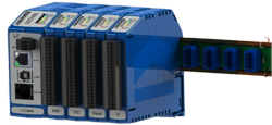
- Install a controller, such as the MAQ®20 PID controller, and connect it to the electronic temperature measurement and the automated control valve.
A PID controller has a Set Point (SP) that the operator can set to the desired temperature. The Controller’s Output (CO) sets the position of the control valve. And the temperature measurement, called the Process Variable (PV), gives the controller its muchneeded feedback. The process variable and controller output are transmitted via current, voltage, or digital signals. When everything is up and running, the PID controller receives the process variable signal, compares it to the set point, and calculates the difference between the two signals, also called the Error (E). Then, based on the error and the PID controller’s tuning constants, the controller calculates an appropriate controller output that sets the control valve to the right position for keeping the temperature at the set point. If the temperature should rise above its set point, the controller will reduce the valve position and vice versa.
PID Control
PID controllers have three control modes:
- Proportional Control
- Integral Control
- Derivative Control
Each of the three modes reacts differently to the error. The amount of response produced by each control mode is adjustable by changing the controller’s tuning settings.
Application Note 122 (AN122) reviews the design of PID controllers and further explains the P, I, and D control modes used in them.