an505: Hardware Linearization of Non-Linear Signals
Application Note
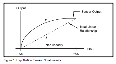
Many sensors used in industry exhibit a deviation from an ideal (linear)
relationship between input and output. For example, a given change in
temperature does not give rise to the same change in emf for most
thermocouples when measured over different temperature ranges. Sensors or
signals which exhibit this behavior are said to be non-linear. A hypothetical
non-linear transfer function is shown in Figure 1.
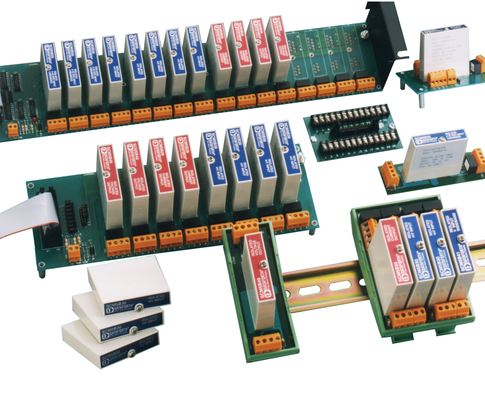
Several of the SCM5B series modules have the capability of creating a non-linear transfer function through the module itself. This non-linear transfer function is configured at the factory and is designed to be equal and opposite to the sensor or signal non-linearity. The net result is that the module output signal is linear with respect to a given input parameter such as temperature. An output signal which has been linearized with hardware internal to the SCM5B modules is beneficial to the customer because it eliminates the need for tedious software routines which determine a linearized signal through the use of high-order polynomials or look-up tables.
A hardware piece-wise linear technique is used in the SCM5B modules to correct the non-linearity of the signal. The difference between the sensor non-linearity and the linearization provided by the SCM5B module is called the Conformity Error. This is a description of how well the linearization technique conforms to the non-linear curve. Breakpoints are placed along the curve so as to equalize the positive and negative conformity errors. SCM5B modules have the capability of using 9 breakpoints (or 10 segments) to correct non-linearity which allows typical conformity of ±0.015% span. A normalized plot of sensor non-linearity and hardware linearization is shown in Figure 2.
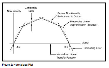
Linearization of a given input is based upon the input minimum and maximum values. For any input within these limits, the output of the module will be a linear representation of the input. If the input exceeds the minimum or maximum values, the output of the module is no longer a linear representation of the signal. This is shown in Figure 2. Operation of an SCM5B module beyond the specified input span is not recommended because the output is difficult to calculate. If a standard module input span does not meet customer requirements a custom module can be easily designed for optimum performance in a given system. Consult the factory for details on custom SCM5B modules.

Several of the SCM5B series modules have the capability of creating a non-linear transfer function through the module itself. This non-linear transfer function is configured at the factory and is designed to be equal and opposite to the sensor or signal non-linearity. The net result is that the module output signal is linear with respect to a given input parameter such as temperature. An output signal which has been linearized with hardware internal to the SCM5B modules is beneficial to the customer because it eliminates the need for tedious software routines which determine a linearized signal through the use of high-order polynomials or look-up tables.
A hardware piece-wise linear technique is used in the SCM5B modules to correct the non-linearity of the signal. The difference between the sensor non-linearity and the linearization provided by the SCM5B module is called the Conformity Error. This is a description of how well the linearization technique conforms to the non-linear curve. Breakpoints are placed along the curve so as to equalize the positive and negative conformity errors. SCM5B modules have the capability of using 9 breakpoints (or 10 segments) to correct non-linearity which allows typical conformity of ±0.015% span. A normalized plot of sensor non-linearity and hardware linearization is shown in Figure 2.

Linearization of a given input is based upon the input minimum and maximum values. For any input within these limits, the output of the module will be a linear representation of the input. If the input exceeds the minimum or maximum values, the output of the module is no longer a linear representation of the signal. This is shown in Figure 2. Operation of an SCM5B module beyond the specified input span is not recommended because the output is difficult to calculate. If a standard module input span does not meet customer requirements a custom module can be easily designed for optimum performance in a given system. Consult the factory for details on custom SCM5B modules.
Was this content helpful?
Thank you for your feedback!


