an801: DSCA Calibration Procedure
Application Note
- Using the module data sheet or module top label, determine the input and output ranges of the module. Connect a
precision voltage source, current source, frequency source, RTD simulator, resistance or thermocouple simulator as
appropriate to the input of the module. Set the input source to the value shown below.

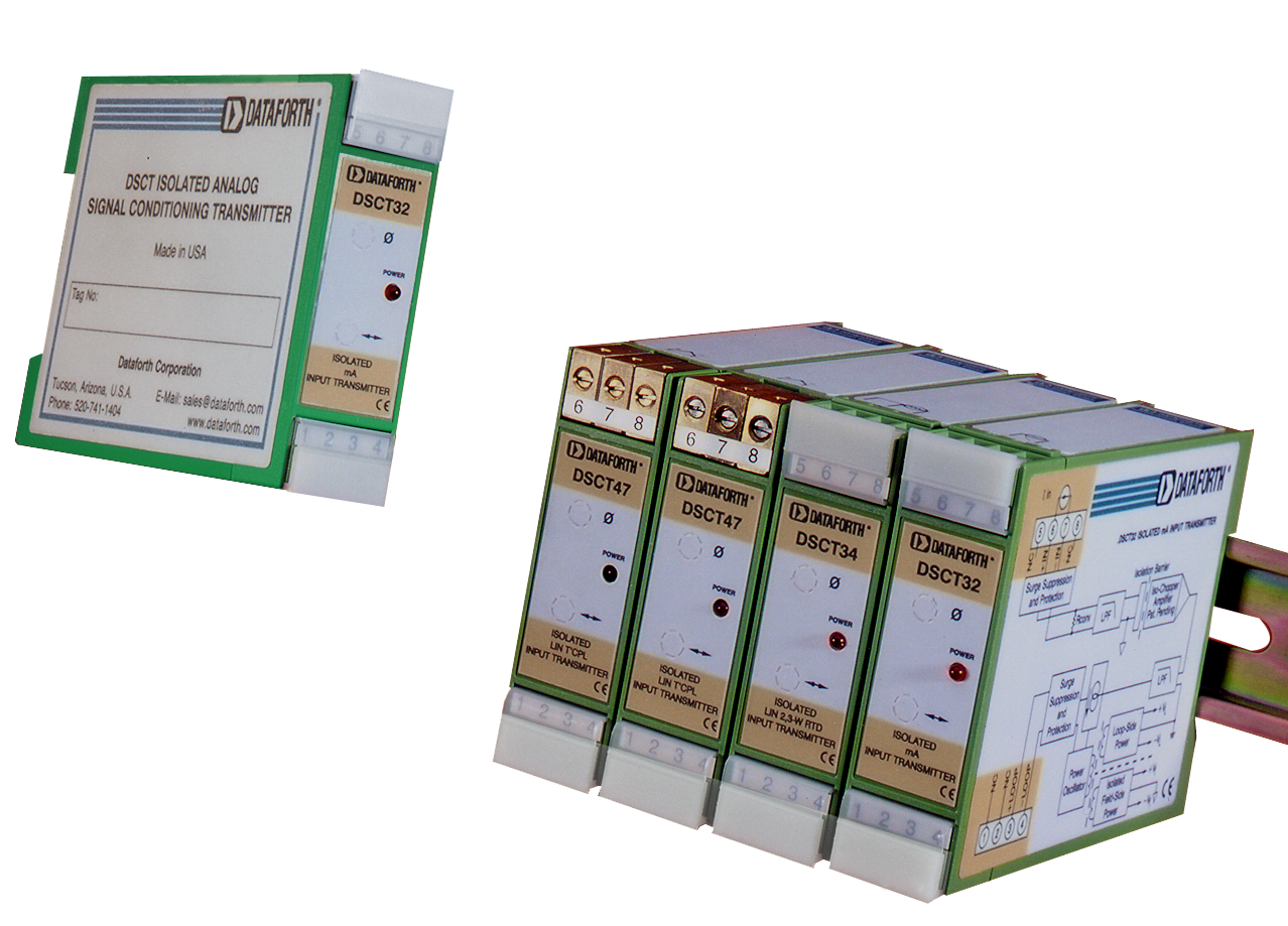
- Locate the required output signal in the table below. Turn the Zero Adjust Potentiometer (marked with the ‘0’ symbol) to
obtain the module output shown:

- Set the module input source to the positive full scale input value
- Turn the Span Adjust Potentiometer (marked with the two-headed arrow symbol) to obtain the positive full scale module output.
** DSCA33-xx requires the following calibration sequence for non-interactive adjustments.
- Set the module input to 10% full scale and record the module output. This is Meas. #1.
- Set the module input to 100% full scale and record the module output. This is Meas. #2.
- Calculate the required module full scale output as follows: Required Output = Meas. #2 1.1*(Meas. #2 Ideal Full Scale Output (Meas. #1 Ideal 10% Output)
- Turn the Span Adjust Potentiometer to obtain the calculated value of Required Output.
- Set the module input to 10% full scale.
- Turn the Offset Adjust Potentiometer to obtain Ideal 10% output. (i.e. 1V for 0V to 10V output module).
Was this content helpful?
Thank you for your feedback!


