Dataforth's 8B33 SCM for Measuring True RMS Now Available
Press Release
Release Date: Feb 13 2009
Dataforth Corporation of Tucson, Arizona, has added another module to its growing family of miniature SensorLex 8B isolated analog signal conditioners: the 8B33, designed for measuring True RMS values of input signals. 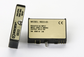
Each 8B33 True RMS input module accepts a single channel of AC input which is converted to its True RMS DC value, then filtered, isolated, amplified, and converted to a standard process voltage or current output.
Key features and specifications of the 8B33 include:
- Interfaces to RMS Voltage (0-300V) or RMS Current (0-1A)
- Designed for Standard Operation with Frequencies of 45Hz to 1000Hz (Extended Range to 10kHz)
- Compatible with Standard Current and Potential Transformers
- ±0.25% Factory Calibrated Accuracy
- 1500Vrms Transformer Isolation
- Input Overload Protected to 350Vrms Max (Peak AC & DC) or 2Arms Continuous
- ANSI/IEEE C37.90.1 Transient Protection
- 120dB CMR
- Industry Standard Output of 0 to 5VDC
- -40°C to +85°C Operating Temperature Range
- CE Compliant
- Hazardous Location Certifications Pending
RMS, or Root Mean Square, is a key measurement of an AC signal. In practical terms, it is the equivalent DC signal that produces the same amount of heat in a given load. Therefore, it directly relates to signal power. For purely sinusoidal signals, the RMS value is the familiar peak amplitude divided by the square root of two. However, for signals comprised either of harmonics or of noncoherent content, this expression becomes increasingly invalid as the harmonic content or noncoherency increases. With these types of signals, therefore, the value is typically given in terms of a waveform's Crest Factor, which is the ratio of its peak amplitude to RMS amplitude. Crest factors start at one for DC or square waves and increase for more "pointed" signals.
By reducing the dependency on sinusoidal purity, True RMS conversion allows accurate measurement of signals ranging from pulses to complex nonperiodic waveforms. The conversion core circuit used in the 8B33 is similar to those found in high-end digital voltmeters.
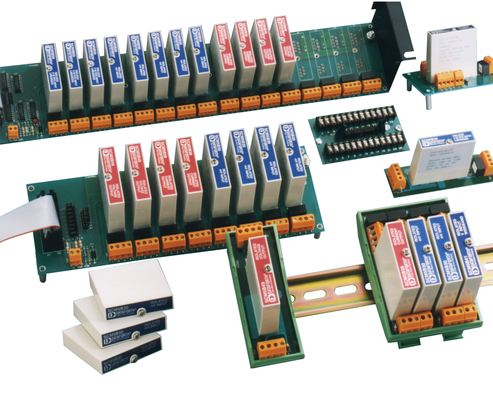
Like all modules in the SensorLex® 8B family, the 8B33 is fully encapsulated and thus able to withstand harsh environmental conditions while providing fully functional Instrument Class performance. Originally developed in response to customer requests worldwide for smaller, lower cost isolated signal conditioners, the SensorLex 8B is housed in a miniature 1.11" x 1.65" x 0.4" (28.1mm x 41.9mm x 10.2mm) module. The product line now includes 19 family groups with a total of 123 different models.
The 8B's small size is ideal for embedded or portable applications such as mobile test stands, COTS military and defense applications, miniaturized security and surveillance systems, embedded process controls for semiconductor manufacturing equipment, and virtually any other embedded industrial data acquisition system.
All 8B modules interface to a wide variety of voltage, current, temperature, position, frequency, and strain measuring devices. Their solidly potted thermoplastic plug-in-the-panel packaging provides excellent impact properties, dimensional stability over temperature, chemical resistance, and a flammability rating of UL-94 V-0. The line is also available in a DIN mount configuration.
Modules that make up the SensorLex® 8B family include voltage and current input modules; linearized 2-, 3-, and 4-wire RTD modules; potentiometer, strain gage, and both linearized and non-linearized thermocouple input modules; current and voltage output modules with 100Hz bandwidth; voltage input modules with 3HZ, 1kHz and 20kHz bandwidths; frequency input modules, and 2-wire transmitter interface modules. Except for those models specified, signal bandwidth is 3Hz for most 8B modules. All modules have excellent stability over time and do not require recalibration.
Analog signals the 8B can interface to include millivolt, volt, milliamp, thermocouple, RTD, potentiometer, slidewire, strain gage, frequency, and 2-wire transmitter. Analog output modules provide a wide selection of current and voltage output ranges.
Voltage input conditioners accept signals from ±10mV to ±60V, and current input conditioners accept signals of 0/4 to 20mA. Accepted thermocouple types are J, K, T, R, and S. Type Pt 100 RTDs can be 2-, 3-, or 4-wire. Potentiometer inputs can range from 0-100 ohms to 0-10k ohms. Strain gage transducers can have a resistance range of 100 ohms to 2k ohms, with sensitivities of 2mV/V or 3mV/V. Frequency input signals can be TTL or zero crossing with ranges from 0-500Hz to 0-100kHz. The 2-wire transmitter module provides loop power and accepts a 4 to 20mA input signal. Additional models offer isolated field-side current and voltage outputs. Current output ranges are 0 to 20 and 4 to 20 milliamp, while voltage output ranges are 0 to 10V and ±10V.
Linearization of thermocouple signals is accomplished by a hardware implemented piece-wise approximation technique. The difference between sensor nonlinearity and the linearization provided by the 8B module is specified as conformity error. 8B modules use up to five segments to correct nonlinearity, which results in conformity errors as low as ±0.015% span. Cold junction compensation error for thermocouple inputs is ±0.5°C at 25°C ambient.
Design-in 8B accessories include a selection of standard and DIN backpanels (1, 2, 4, 8, and 16 channels) that provide screw-terminal inputs and outputs, as well as a DB25 header connector. The DB25 cables are available in 1, 2, or 7 meter lengths. Moreover, a power supply module in the same 8B form-factor is offered to accommodate input voltages of 7 to 34VDC and provide 5VDC output at 2A to power any combination of 8B signal conditioners. This 8BPWR-2 module plugs into its own socket on the backpanel. A DIN rail mounting accessory, the 8BP01, is offered as a 5VDC powered or 7 to 34VDC powered DIN rail mount carrier suitable for any 8B module. The 8B carrier can be mounted on any standard DIN rail (EN 50022-35 and EN 50035-G32).
Each 8B module isolates the field-side input or output signal with an optical or galvanic isolation barrier rated at 1500Vrms. Common-mode rejection is 120dB; by incorporating a 5-pole filter, normal-mode rejection is 85dB at 60Hz.
Operation and storage temperature is -40 C to +85 C, and relative humidity range is zero to 95% noncondensing. All models are CE Compliant and meet the requirements of EN61000-6-4 (radiated/conducted emissions) and EN61000-6-2 (ESD/RF/EFT immunity). For operation in hazardous environments, North American Class I, Division 2, and European Group II, Category 3, approvals are pending.
Dataforth Corporation was established in 1984 and is a worldwide leader in the design and manufacture of signal conditioning, data acquisition, and data communication products for industrial and institutional markets. The company is ISO9001:2015 registered. For additional information, call 800-444-7644 toll-free, or e-mail sales@dataforth.com.
Original Release: February 2009, updated August 2009
Was this content helpful?
Thank you for your feedback!

